Physical design and build
The hull, structure and internal layout of a self-positioning slalom buoy — and what it takes to build one. Off-the-shelf parts throughout: a drill, a saw and a soldering iron, with no machining and no 3D printing required.
The rule that shapes everything
Nothing hard where a skier can reach it. Everything above the waterline is rubber, foam or flexible hose. That single requirement drives the entire architecture — it is why the antenna lives inside a foam marker, why the hatch is a push-on rubber cap, and why the mast is a length of hose that folds away rather than a pole that resists.
Working alongside it, the requirements that matter most to the shape:
| Self-righting | Rights itself from any angle of heel; metacentric height at least 40 mm |
| No heel under thrust | Under 8°, because a tilted antenna degrades the position fix and a tilted hull vectors thrust downward |
| Compass integrity | No ferromagnetic ballast or fasteners near the magnetometer — lead ballast, brass, nylon and 316 stainless only, and the motors 380 mm away. The acceptance test is blunt: a magnet must find nothing within 100 mm of the compass |
| One-person handling | Under 16 kg all-up, with a carry point, and it fits in a car |
| Opens on the bench only | Charging and power on/off are reachable from outside, so the hull stays sealed on the water |
| Survives a strike afloat | Stays sealed and buoyant even with the marker and masthead torn off |
| Endurance | At least four hours of station-keeping per charge |
| Propeller safety | Shrouded and at least 400 mm below the surface, for skiers and for weed |
Why a spar
A spar buoy — a long, thin vertical cylinder ballasted at the bottom — is the textbook shape for staying still in chop. Its waterplane is tiny, so waves pass it rather than lift it, and the bottom ballast turns the whole hull into a self-righting pendulum.
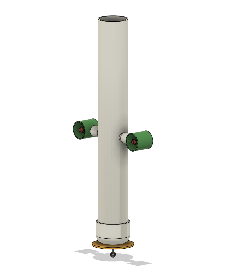
- Red foam marker Eight 180 mm lengths of red pool noodle standing in a ring 235 mm across. A skier meets 65 mm of foam before anything solid.
- Pod The antenna, the Feather and the charge/ON connector, sealed in at z 977–1041. Foam is transparent to radio, so the marker is the radome.
- Flexible stalk Two barb fittings joined by hose with 35 mm left free (z 874–977), so a knock bends it rather than breaking it.
- Rubber hatch cap A clamped Fernco cap over the pipe rim, z 832–874. It does not rotate, so nothing attached to it twists.
- Still waterline The dashed rule. It sits at the cap’s lower edge: 832 mm of draft, with 34 mm of pipe rim standing above the water.
- Electronics sled z 415–806, seated on the two strut stubs and lifted out on a cord — not hung from the hatch. It carries both motor controllers, the carrier board, the GPS board and the compass.
- Thrusters, at half draft Strut stubs at z 416, pod axes 300 mm apart, propellers 416 mm under the surface. Thrust acts through the centre of lateral resistance, so full thrust heels the hull 0.0° instead of 47.1°.
- Battery Two stock 6 Ah LiFePO4 packs on end at z 75–296, below the thrusters, joined by a fused Y-harness. Turned 64 mm side to the stubs, they pass the 72 mm gap with 4 mm to spare each side.
- Lead ballast z 10–53, loose in bags for the float test and potted only afterwards. Lead, never steel, so the compass stays honest.
- 160 mm skirt disc and eye bolt The disc damps heave; the eye bolt is the carry point — never pick the buoy up by a thruster pod.
A render of the finished buoy with the port half of the hull removed, so the sled, both battery packs, the ballast and the wiring are visible on their assembled routes. z is millimetres above the hull’s outside bottom.
The marker is the radome
The antenna has to be above water and nothing hard may be exposed. Foam is transparent to radio, so the antenna lives inside the marker. A skier meets 65 mm of foam before anything solid.
Thrusters at half draft
Thrust is reacted by hull drag at the centre of lateral resistance — half draft for a uniform spar. Put the thrusters there and the heeling couple is zero by geometry: 0.0° against 47.1° for a low mount.
The sled is keyed to the stubs
A 90 mm saddle block at the plate's foot drops over both stubs and bridges the gap. That sets the sled's height and its heading, so the compass returns at the same angle however the hatch went on.
The strut is two stubs, not one tube — and the reason is a good illustration of how the internal layout constrains the structure. Each pod hangs on a 54 mm stub of 1" pipe epoxied through its own side of the hull. A single tube running across the bore would leave only 34 mm of clearance each side of it, and the battery — 64 mm thick, and living below the thrusters — could then never be put in or taken out. The stubs leave 72 mm clear between their tips, which the packs clear by 4 mm a side.
The numbers
| Hull | 834 mm of 4" schedule-40 PVC pipe |
| Draft | 832 mm — the rim floats 34 mm above still water |
| All-up mass | 9.0 kg |
| Ballast | 2.14 kg nominal, as loose lead for the float test. Afterwards 1.74 kg potted, with 0.25 kg left loose for trimming |
| Metacentric height | 73 mm (requirement: 40 mm) |
| Heel at full thrust | 0.0° |
| Thruster axis | 450 mm below the rim; pod axes 300 mm apart, propellers 416 mm under the surface |
| Heave period | 1.9 s — at the bottom of the boat-wake band, hence the skirt disc |
| Draft sensitivity | about 10 g per mm |
| Endurance | 4.7 h at 10% thrust duty, on 12 Ah |
| Heel in an 18 mph wind | about 8° on the marker |
One constraint governs everything that goes down the pipe: a rectangular part fits the 102 mm bore only if its diagonal does. That is why the battery is two stock 6 Ah packs standing on end rather than one 12 Ah brick — no stock 12 Ah pack is thin enough for a 4" pipe, while the 6 Ah size has a 94 mm diagonal and clears it. Turned 64 mm side to the stubs they also pass the gap below the thrusters, and stacked they come to 221 mm, short enough for an 834 mm hull. Keeping the battery a catalogue part rather than a made-to-order one is deliberate; the cost is that two packs in parallel must be matched and individually fused.
Three modules, one screwdriver
| Module | What it is | Serviced |
|---|---|---|
| Hull | The pipe, the bottom cap with its lead ballast, the two strut stubs carrying the thruster pods, and the battery | Stays put |
| Sled | A plate carrying both motor controllers, the carrier board, the GPS board and the compass. It sits on the strut stubs inside the pipe | Lifts out |
| Hatch & masthead | The rubber cap, the flexible stalk, the pod and the foam marker | Lifts off |
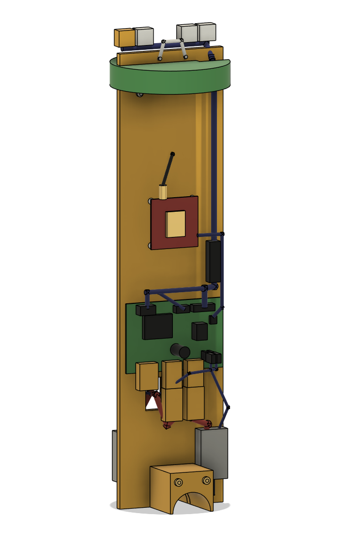
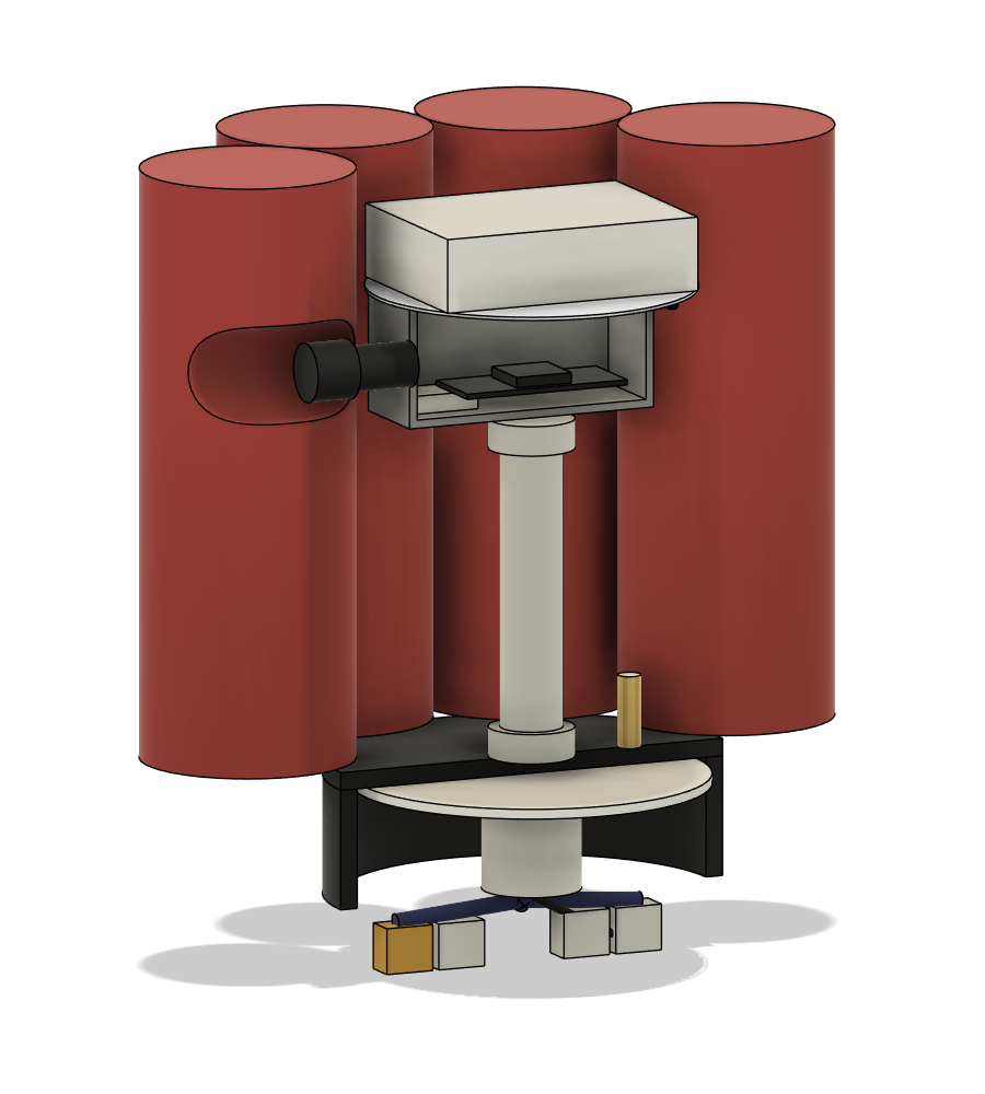
Two sets of connectors join them, with service loops long enough that the sled rises clear of the rim before anything is unplugged. Nothing ever has to be reached for down the pipe.
Building one
About fourteen hours of work, but spread across five days — and the days are set by cure times, not by effort. Solvent welds and slow epoxy want overnight, and below 15 °C everything takes twice as long. Two of those days exist only because the ballast is poured last.
| Day | Steps | Left to cure overnight |
|---|---|---|
| One | Pipe, bottom cap, pod end caps, strut stubs | Cap weld, pod potting, stub epoxy |
| Two | Hatch cap, sled, masthead; pods cemented on last | Masthead potting, pod-cap welds |
| Three | Pressure test, loose ballast, battery, assembly, bench test, float trim | — |
| Four | Pot the ballast | Ballast epoxy |
| Five | Reassemble, re-check, first water | — |
The lead goes in loose first, and is potted only after the float test. How much ballast a hull actually needs depends on what its parts really weigh, and several of those weights are estimates in the model. So the shot goes in as loose bags, the buoy is floated to find the true figure, and only then is it epoxied down — all but about a quarter of a kilo, which stays loose so the trim can still be moved either way later.
- Cut, mark and drill the hull pipeEvery hole is set out before anything is glued.
- Bottom cap, skirt disc and eye boltThe carry point and the heave-damping disc.
- Pod end capsThe thruster pods are sealed units.
- Strut stubsTwo short lengths of pipe epoxied through the hull sides at half draft.
- Hatch capA rubber cap over the bare rim, with a stiff backing disc inside.
- Electronics sledPlate and saddle, mount the parts, wire it, top collar and lifting loop.
- MastheadPod box, connector, antenna, stalk, potting, marker.
- Fit the pods to the stubsCemented on last, once everything else has cured.
- Pressure testSoapy water and a floor pump, before electronics go anywhere near water.
- Ballast, first fitLoose bags of lead shot — the amount is still provisional.
- BatteryTwo stock packs on end, matched and fused, in the only orientation the bore allows.
- Final assemblySled in, masthead on, connectors made up.
- Bench testConfirming the thrusters reverse and come to a true stop, before anything gets wet.
- Seal test, compass and float trimThe float test sets the true ballast figure.
- Pot the ballast, final checks, first waterNow that the number is known, the lead is epoxied down.
Tools
A hacksaw or mitre saw and a file; a drill with bits up to 8.5 mm and a step bit; a 35 mm hole saw for the strut holes and the sled's saddle notch; a jigsaw and tin snips; calipers, square and rule; a kitchen scale for ballast and epoxy and a luggage scale for mass and thrust; a soldering iron and heat gun; a bicycle floor pump with a gauge and a spray bottle of soapy water for the pressure tests; a multimeter. Plus PVC primer and cement, slow-cure epoxy, epoxy putty, marine sealant and the usual consumables.
Where it can bite
The design documents its own failure modes rather than hiding them. The ones that matter:
| Risk | What is done about it |
|---|---|
| A flooded hull sinks | Full of water it is several kilograms heavier than the water it displaces. Two pressure tests, a thirty-minute float check, inspection after the first few outings, and a retrieval line with a float until a new buoy has earned trust |
| Heave resonance | The 1.9 s natural period sits at the bottom of the boat-wake band. The skirt disc adds damping; a wider disc is one nut away if bobbing is objectionable |
| The hatch is a low-pressure rubber cap at the waterline | Static head at its lower edge is nil. Pressure-test each season, re-check the clamp at each launch, replace the cap when the rubber chalks |
| Thruster stop and reverse | 1500 µs is stop and below it is reverse. The fitted ESCs do reverse, but each fixes its neutral band when it arms and the band need not be centred on 1500 µs, so the props can creep after a stop. A per-ESC stop trim is set on the bench and saved; an ESC that will not reverse is replaced with a bidirectional one |
| Two packs in parallel, each with its own protection board | The maker does not recommend parallel use without matching and fuses, so the packs are matched within 0.1 V before joining and each lead carries its own fuse. If one board trips the other takes the load until it trips too, so the buoy stops rather than failing unsafe |
| Shrouds degrade in water and UV | Pods are treated as consumables, each with an external lead loop so a replacement splices on outside the potting |
Parts
A fully itemised parts list and order — every fitting, fastener and consumable, with quantities and sources — is maintained with the project but is not published here. The build guide below walks the assembly itself.